
An overview of UPDM - A Unified Profile for DoDAF/MODAF
StoryOctober 24, 2008

Matthew Hause
Artisan Software Tools
Amidst a plethora of differing military architectural frameworks arises the new Unified Profile for DoDAF and MODAF (UPDM), which aims to create a standardized UML/SysML profile for these and other military frameworks.
A veritable Tower of Babel of military architectural
frameworks, such as DoDAF, MODAF, NAF, DNDAF, and ADOAF, is emerging. Each one
adds to, redefines, and/or clarifies the concepts, viewpoints, and concerns
contained within military Architectural Frameworks, with the intention of
improving procurement, planning, and implementation of military systems.
However, supporting multiple and sometimes divergent frameworks leads to
problems for industry, military organizations, and tool vendors alike.
In this age of globalization, mil-aero companies provide
systems across the world to multiple governments. Often they must be specified
in the local Architectural Framework, creating extra overheads. Incompatible
frameworks cause interoperability problems between governments because models
cannot be exchanged. Interchange, even between modeling tools supporting the
same framework, is difficult, if not impossible due to the different underlying
implementations. Finally, having to support several constantly changing
framework formats means that modeling tool vendors have a support nightmare.
What is a Military Architectural Framework?
Military Architectural Frameworks such as DoDAF define a
standard way to organize an Enterprise Architecture (EA) or systems
architecture into complementary and consistent views. DoDAF contains four basic
views: the overarching All View (AV), Operational View (OV), Systems View (SV),
and the Technical Standards View (TV). Each view is aimed at different
stakeholders, and it is possible to create cross-references between the views.
Although they were originally created for military systems, they are commonly
used by the private, public, and voluntary sectors around the world to model
complex organizations such as humanitarian relief organizations and public
services such as FEMA. Their goal is to improve planning, organization,
procurement, and management of these complex organizations. All major DoD weapons
and information technology system procurements are required to document their
enterprise architectures using DoDAF.
Fortunately, using the Unified Modeling Language (UML)
- as extended by the recently created Systems Modeling Language (SysML)
- as an underlying mechanism for all of these military Architectural Frameworks
makes it feasible to work toward a standardized UML/SysML profile. UML is a
visual modeling language for software and can be extended to include new
concepts using what is called a Profile,
which provides a means to create and extend elements found in UML. SysML, which includes new concepts such as enhanced
interface and flow specifications, system concepts, parametrics, integrated
requirements, and others, is an example of a UML Profile.
Arguably, the two most widely used frameworks are the
Department of Defense (DoD) Architecture Framework (DoDAF) in the USA and the
Ministry of Defence (MOD) Architecture Framework (MODAF) in the UK. In March
2008, the UPDM Group was re-formed by members of INCOSE and the OMG to create
the Unified Profile for DoDAF and MODAF
(UPDM) using UML/SysML.
Whoís who in UPDM
Members of the UPDM Group are tool vendors Adaptive, Artisan
Software Tools, EmbeddedPlus, No Magic, Sparx, Visumpoint, members of industry
ASMG, BAE Systems, Generic AB, Lockheed Martin, Mitre, Raytheon, Rolls Royce,
and representatives from the DoD, MOD, and NATO. Members of the DoDAF 2.0 task force
were heavily involved to ensure that DoDAF 2.0 and UPDM converged as much as
possible. Finally, members of the Canadian DND also participated. The DoD and
MOD have officially issued a definitive statement of support for UPDM (see www.omg.org). Through coordinated teamwork, many
of the challenges have already been overcome. This results in a specification
that has been accepted by the OMG and is fully endorsed by both the DoD and MOD.
The goals of UPDM are to significantly enhance the quality,
productivity, and effectiveness associated with enterprise and system-of-systems
architecture modeling, promote architecture model reuse and maintainability,
improve tool interoperability and communications between stakeholders, and
reduce training impact due to different tool implementations and semantics.
Using the UML XML Metadata Interchange (XMI) interchange format, virtually all
UML tools will be able to exchange models. Standardization of views means that
both tool vendors and industry can provide models in a single format.
Customized views can still be created, but they are based on core UPDM rather
than requiring bespoke development. Finally, the UML/SysML foundation will
improve the integration between Architectural Framework modeling and system
modeling to support post-acquisition life-cycle design and implementation.
It is important to stress that UPDM is not a new Architectural Framework. Instead, it provides
a consistent, standardized means to describe DoDAF and MODAF architectures in
UML-based tools as well as a standard for interchange. We will provide an
overview of UPDM development, views unfamiliar to DoDAF modelers, and our
future goals.
Background to UPDM
Model-based engineering is at the heart of the Architectural
Framework approach to modeling. A model of the system is created using
different views to denote different stakeholder interests, and to provide a
means for evaluation and report generation as well as to simplify maintenance.
In the desire to "walk our talk," UPDM is also being developed using a
model-driven approach.
In terms of the UPDM work process, a Domain Metamodel (DMM)
was created using UML Class models to represent the concepts in DoDAF and
MODAF. The DMM was the requirements model for UPDM, and traceability links
between the DMM and the UPDM model were created. Concepts common to both DoDAF
and MODAF were captured in a core package. The DMM concepts were then mapped to
corresponding stereotypes in the Profile, which was analyzed and refactored to
reflect language architecture, tool implementation, and reuse considerations.
The conformance levels were finalized including mapping to SysML, the Profile
diagrams, stereotype descriptions, and documentation were added.
Finally, the specification and XMI document were generated
from the Profile model. This model-based approach allowed the team to
concentrate on architecture issues rather than documentation production.
Consistency was automatically maintained by the UML tool. With every stereotype
linked to the DMM element, the UML tool also enabled requirements traceability
to be maintained between the Profile and the DMM.
Architectural Frameworks used in UPDM
The core views in DoDAF - All Views, Operational,
Systems, and Technical - have been used successfully to define military
architectures for some time now. However, system architects found that these
views did not go far enough. Although these views are aimed at getting the "big
picture" and were sufficient for managing large projects, practitioners found
that DoDAF was not actually big enough to properly counter the issue of
"stovepipe development". This is where military procurements are developed in
isolation from each other rather than in a coordinated manner, resulting in the
creation of incompatible and redundant systems, resulting in higher development
costs, unnecessary expenditures, and inefficient military operating procedures.
One example of this was a ground support helicopter deployed
with a communications system that was incompatible with the ground troopsí
radios. This meant that all communication had to be routed through the command
base. They also found that DoDAF lacked the breadth necessary for effective
program management, where the goal is to specify multiple projects in order to
develop compatible capabilities.
Meanwhile, MODAF kept compatibility with the core DoDAF
viewpoints in order to facilitate interpretation of architectural information
with the U.S. However, MODAF v1.1 added two new viewpoints: the Strategic and
Acquisition Viewpoints. These were added to better contribute to MOD processes
and life cycles, specifically the analysis of the strategic issues and
dependencies across the entire portfolio of available military capabilities
within a given timeframe. In MODAF v1.2, Service Views were added to support
the development of Service Oriented Architectures (SOA).
In the same way that the DoDAF views are integrated into UPDM,
MODAF views are as well. For example, UPDMís Acquisition Views specify when the
capabilities defined within the Strategic Views will become available.
Capabilities can be associated with capability configurations that define the
systems, organizations, and people necessary to achieve the capability.
Detailing all of the new views is a task for a book, and not an article.
Consequently, we will simply give you an overview of views unfamiliar to DoDAF
modelers, and some examples of these views. The following example pertains to a
Search and Rescue (SAR) set of capabilities - such as mountain SAR,
maritime SAR, battlefield SAR, and so forth - and covers the
Capability/Strategic View, the Acquisition View, and the Service-Oriented View.
Capability/Strategic View
The Strategic View provides a high-level view of the
enterprise capabilities and their relationships, enabling Capability
Management, for example, capability introduction, integration, realignment, and
removal. A capability is the ability or capacity to achieve specific
objectives. Examples include Search and Rescue, effects delivery,
transportation, and so on. A single Strategic View can be defined that will
have a number of Architecture Descriptions. Each Architecture Description may
then have multiple Operational, System, Technical Standards, and All Views.
UPDM comprises six Strategic Views.
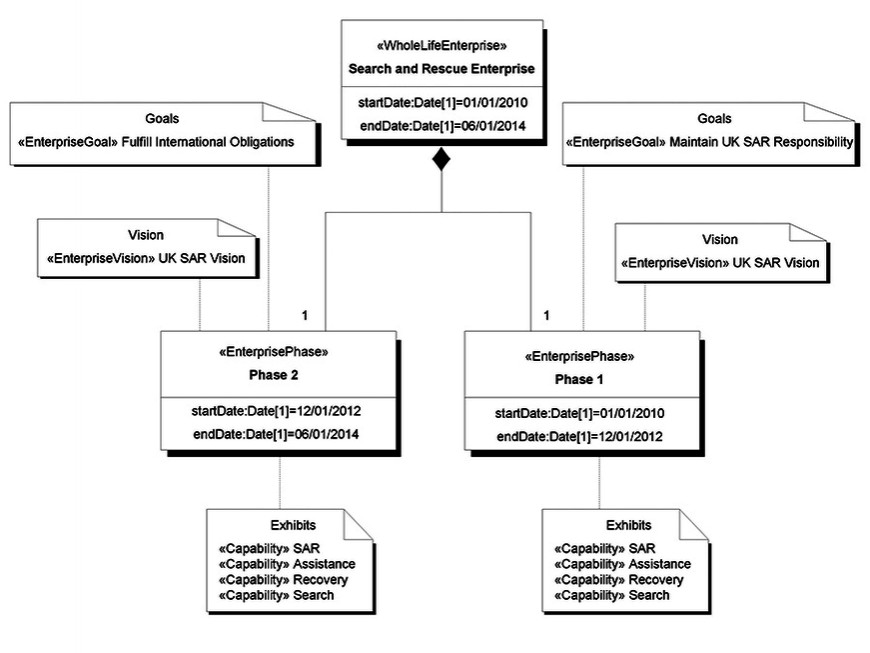
The StV-1 Enterprise Vision defines Enterprise Goals and
Visions relating to a time-based Enterprise Phase. For example, Figure 1
describes the strategic context for a Search and Rescue (SAR) project. It
outlines the vision for a capability area over a specified period of time. It
also describes how high-level goals and strategy are to be delivered in terms
of capability.
Figure 1
(Click graphic to zoom by 2.5x)
|
|
The StV-2 Capability Taxonomy defines capabilities for
current and future enterprises in a hierarchy and the environmental conditions
associated with the different capabilities, while the StV-3 Capability Phasing
view shows when capabilities will be available and/or decommissioned over
specific periods of time and how they relate to projects. StV-4 Capability
Dependencies describes the capabilities in logical groups and the dependencies
between the capabilities, and StV-5 - Capability to Organization
Deployment Mapping - shows how capabilities map to organizations and the
capability configurations that will achieve the capability. Finally, StV-6
Operational Activity to Capability Mapping shows which Operational Activities
map to which capabilities.
Acquisition View
The Acquisition View describes project details and
dependencies between projects and capability integration. This helps to guide
the acquisition and deployment processes. The views are as follows:
- AcV-1 Acquisition Clusters View - This enables the user to
model the organizations and projects. It shows the dependencies between the
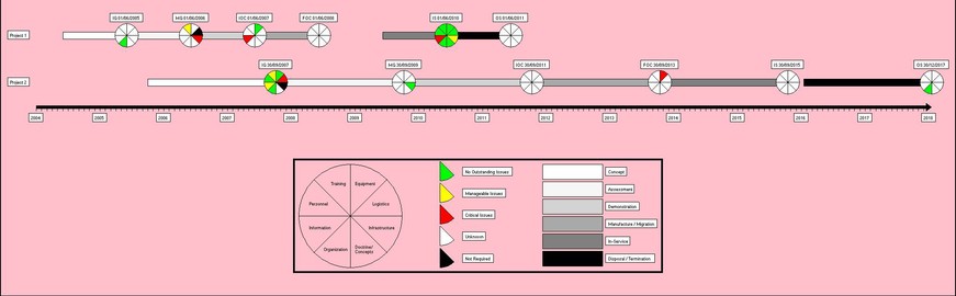
actual organizations that own projects. - AcV-2 Program Timelines View - This view defines project
timelines and their relationship to Capability Configurations. It supports
acquisition and deployment including the management of dependencies between
projects and the integration of the Defense Lines of Development (DLOD) to
achieve a successfully integrated military capability. The DLOD are training,
equipment, personnel, information, concepts and doctrine, organization,
infrastructure, and logistics. Figure 2 shows AcV-2 Program Timelines View for
the SAR project. It details the milestones along with a pie chart showing the
DLOD levels of completion.
Figure 2
(Click graphic to zoom by 2.5x)
|
|
Service-Oriented View
The Service-Oriented View is a description of services needed
to directly support the operational domain as described in the Operational View.
A service is described as a unit of work through which a particular Resource
provides a useful result to a consuming Resource. UPDM services may include
standard Web-based services, but also define effects deployment, logistics
support, and even cooking meals for hungry soldiers. The resource provides the
service, and the consuming resource makes use of it. The Services Views are the
following:
- SOV-1 Service Taxonomy - This view describes services in a
generalization hierarchy, showing services that are types of other services. - SOV-2 Service Interface Specification - Describes the
provided and required interfaces for services, such as what they will do and
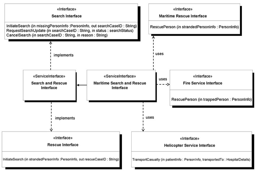
what they need. - SOV-3 Capability to Service Mapping - Displays how services
support capabilities. Figure 3 shows a SOV-3 Capability and Service Mapping
diagram. It defines the interfaces that will provide access to the services for
SAR.
Figure 3
(Click graphic to zoom by 2.5x)
|
|
- SOV-4a Service Constraints, SOV-4b Service State Model, and
SOV-4c Service Interaction Specification - These describe service
policies, state-based behavior, and interactions for a service in general. - SOV-5 Service Functionality - Describes functions and
operations that the service will perform.
Future direction of UPDM
The UPDM specification 1.0 was delivered to the Object
Management Group (OMG) on August 25, 2008, and was voted on and accepted during
the OMG September meeting. Comments from OMG members and the public in general
can be sent to the OMG. Once these comments have been addressed, the specification
will be voted on again during the OMG December meeting. It will then go through
a Finalization Task Force, which will address any problems found during the
three-month evaluation period. After this work is complete, it will be voted on
to possibly become an adopted specification. Tool vendors, including Artisan
Software Tools, have already started implementing UPDM in the expectation of
its approval. Implementation will vary, but the intention will be to allow the
Profile to provide DoDAF, MODAF, and UPDM compliant models.
However, the work of the UPDM Group will not stop with DoDAF
1.5 and MODAF 1.2. A new initiative will be launched as soon as it is complete
to cover other Architectural Frameworks. DoDAF v2.0 will be released in 2009,
and the intention is to create a new version of UPDM to maintain exchange compliance.
The NATO Architectural Framework (NAF), which is very similar to MODAF v1.2,
will also be addressed. Finally, the Security Views in the Canadian DNDAF will
be included. While exclusive users of DoDAF may think that this information is
irrelevant, they should be aware that many of the views in UPDM will be
included in DoDAF v2.0.
For more information on UPDM, visit the Artisan website (www.ArtisanSoftwareTools.com)
the UPDM website (www.UPDMGroup.com), or
the OMG website (www.OMG.org).
Matthew Hause, chief
consultant at Artisan Software Tools and co-chair of the UPDM Group, has been
developing real-time systems for almost 30 years. He started out working in the
power systems industry, and has been involved in process control,
communications, SCADA, distributed control, and many other areas of real-time
systems. His roles have varied from project manager to developer. His role at
Artisan includes mentoring, sales presentations and training courses. He has
written a series of white papers on project management, systems engineering,
and systems development with UML, SysML, and Architectural Frameworks. He has
been a regular presenter at INCOSE, the IEEE, BCS, the IET, and other
conferences. Matthew studied Electrical Engineering at the University of New
Mexico and Computer Science at the University of Houston, Texas. He can be
contacted at [email protected].
Artisan Software Tools
+44 (0) 1242 229300
www.ArtisanSoftwareTools.com


