
Using thermofluid simulation to optimize liquid cooling of avionics power systems
StoryFebruary 15, 2018

Mike Croegaert
Mentor

Liquid cooling for military signal processing offers advantages in high-power-density systems to dissipate heat at a higher rate than air-cooled systems and to transfer heat further away efficiently for thermal signature control. When using liquid-cooling systems, the challenge is to meet size, weight, and power (SWaP) goals while ensuring design for performance and reliability. A method is presented on how to model, characterize, and optimize the performance of cold-plate designs using 3-D computer-aided design (CAD)-embedded computational fluid dynamics (CFD) simulations to then immediately use this data in a system-level, fluid-dynamics simulation model of a full-pumped, liquid-cooling system. This 1-D/3-D CFD, model-based design approach enables earlier and more accurate evaluation of physical components.
Advanced avionics, radar, and weaponry control are all significant sources of heat within the fuselage of a military aircraft. The power supplies used to support these electronics also create heat. As more functions are computerized and electronics are smaller, packed into tighter spaces, dissipating this heat gets complicated. Proper cooling cannot be done without enough space for the air to flow. As the heat builds up in the fuselage, it has to be dissipated from the instrument panel and cockpit.
Composites used to build a lightweight aircraft structure and to block heat signatures from detection cannot be used, when considering thermal design, to dissipate heat generated by the interior electronics. Waste heat must be dissipated by other means such as ducting or active cooling devices. The need for alternative means of extracting heat from the avionics systems has led to advances in the development of liquid-cooled electronic components. Liquid-cooled systems have a much higher heat-transfer rate than air-cooled, and heat can be transported further from the source.
However, cooling avionics with liquid has its challenges as well: Traditional air-cooled heat sinks are replaced with cold plates that have internal passageways designed to circulate coolant and absorb the heat from the electronics. The coolant is pumped through a heat exchanger or a series of heat exchangers to extract the heat. The cooling medium can either be air or another liquid or a hybrid system that uses a combination of both air and liquid cooling. The architecture of the components (cold plates, etc.) used for extracting the heat from the electronics component must be optimized to perform consistently and reliably while maintaining the smallest footprint possible. Additionally, these systems require piping, pumps, valves, and controls as well as a heat sink. In most military applications, the heat sink is the fuel.
Using the fuel of an aircraft as a heat sink was considered as far back as the late 1960s and early 1970s, when joint research by General Electric and the Wright-Patterson Air Force base looked into the heat capacity of the fuel for different regional and flight profiles [1]. The concept has garnered interest again as the industry sees advancement in aircraft structures and electronics and the desire to keep the heat and radar signature of the aircraft as small as possible.
A good example of a liquid-cooling system is the one used on the F-22 Raptor. The coolant, polyalphaolefin (PAO), is circulated through the cold plates of the mission-critical electronics in the cockpit and pumped out to the wings to cool remote, embedded sensors. From there, the warm PAO passes through an air-cycle machine where it absorbs even more heat before being sent through a heat exchanger that dumps the heat from the PAO to the fuel.
The real challenge of these cooling systems is to create an optimized design that keeps the mission-critical electronics at their desired operating temperature of 68 °F [2], working properly no matter the mission and flight profile, whether the fuel tank is full (large heat sink) or nearly empty (small heat sink). To achieve this, the cold plates, piping system, and heat exchangers must be designed simultaneously to determine how they interact with each other. The design validation of the cold plates can be done with 3-D thermal simulation and analysis to find the best option for the internal geometry: whether it should contain pins, fins, or open passageways and whether the fins are aligned or staggered.
Three-dimensional thermal simulation provides highly accurate results for the performance of the cold plate; however, trying to model the entire cooling system with such a tool would result in an enormous mesh size and would take too long. In such cases where component location, sizing, and heat exchanger performance are the critical aspects, a 1-D tool is effective for a full-system simulation.
Optimizing at the system level
The example we look at here is similar to the situation on the F-22 Raptor, although the exact system parameters were not used because this information is not publicly available. The overall layout is shown in Figure 1. For simplification, only one of the liquid-cooled cold plates was modeled.
Figure 1: Simplified layout of the liquid-cooled avionics is shown.
|
|
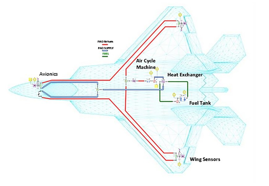
All the other cooled components were modeled as simple lumped parameter components. This can be seen in a close-up view of the cockpit (Figure 2). The blue lines represent the piping containing the cold PAO sent to the cold plates, and the red lines represent the warm PAO leaving the cold plates and going to the wing sensors and the air-cycle machine. The green lines represent the fuel circuit used for cooling the PAO.
Figure 2: Close-up of the cockpit with liquid-cooled cold plate is shown.
|
|

For optimizing the system, five different cold-plate designs were considered. Once these designs were evaluated in the 3-D thermal-simulation tool, they were compared for their standalone performance and how well they perform in the system as a whole.
Evaluating cold-plate designs
The main influences to consider in the thermal design of the cold plates are fluid velocity, heat transfer area, and the comparable ratios of size, weight, power, and cost (SWaP-C).
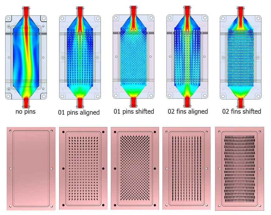
An increase of the fluid velocity increases the heat-transfer coefficient. This leads to a higher heat flow rate, which leads to lower chip temperatures. At the same time, higher velocities cause an increased pressure drop, which increases the energy consumption for pumps. The heat-transfer surface area can be changed significantly by adding enhanced surfaces such as pins or fins (Figure 3). The effectiveness of these enhanced surfaces depends on their arrangement and aligned or shifted patterns. For example, a shifted arrangement usually leads to a higher heat flow rate compared to an aligned arrangement, but at the same time leads to an increased pressure drop.
Figure 3: The five possible geometry configurations for the cold plate designs that were simulated (top) are shown. CAD models from left to right: no enhanced heat transfer, aligned pins, shifted pins, aligned fins, shifted fins (bottom).
|
|
The enhanced features also can have a significant impact on SWaP-C, as the additional surface area affects the size and weight of the cold plate. Additional material is required to construct the enhanced surfaces, which increases cost because of more complex tooling and manufacturing requirements.
Simulating the cold plates
In this example, the cold plates and associated electronics (insulated gate bipolar transistors [IGBTs] and diodes) were constructed in the Siemens NX CAD program and meshed with Mentor’s CAD-embedded thermal-simulation software inside the NX interface. The IGBT chips and diodes were the heat sources: 360 W and 144 W, respectively. Simulations were run for each cold-plate design at a volumetric flow rate of 5 liters (L)/min, and the results were compared. The time to complete one analysis run of this model was 4.5 hours with a person interacting for 2.5 hours on a four-core computer (Table 1). A 16-core machine was used to conduct a 16-run parametric study, which was completed in 16 hours.
Table 1: Analysis statistics for the 3-D thermal simulation of the liquid-cooled cold plate.
|
|
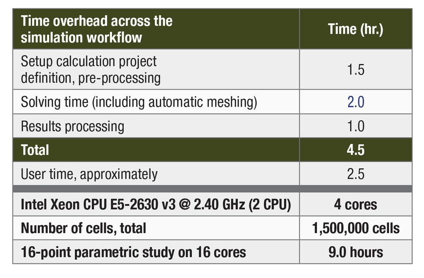
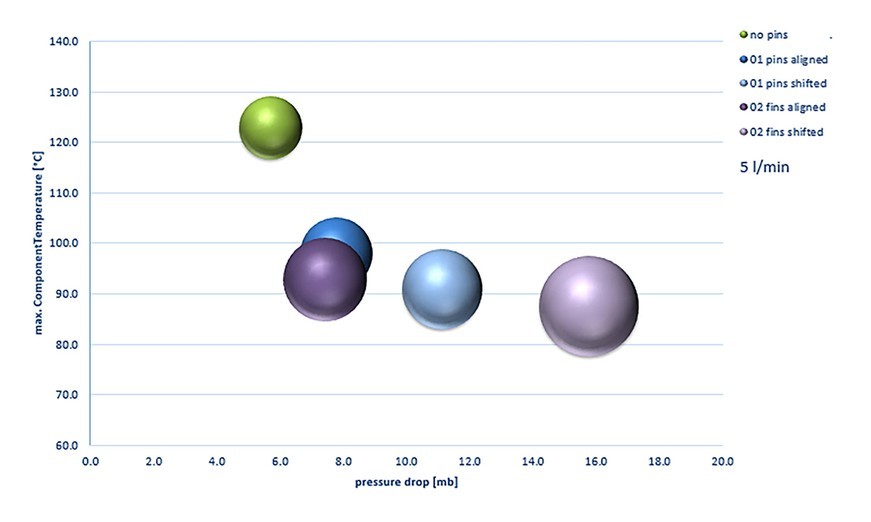
Figure 4 shows that the design without any enhanced heat-transfer surfaces had the lowest weight and the lowest pressure drop but also the highest operating temperature, significantly higher than all the other designs. The other designs were more similar in operating temperatures, but pressure drop varied greatly. The shifted-fin design had the highest pressure drop and was the heaviest of the designs.
Figure 4: Pressure drop versus operating temperature and weight of cold-plate designs is shown. Bubble size represents the relative weight of cold plate.
|
|
A parametric study of each design was also conducted by varying the volumetric flow-rate boundary condition from 1.5 to 5 L/min. Figure 5 shows that all the cold-plate designs that had enhanced heat-transfer surfaces performed similarly for heat dissipation at a flow rate of 1.5 L/min and above, but pressure drop differed significantly between the aligned and shifted designs. The shifted designs had a 50 to 100 percent higher pressure drop than the aligned designs.
Figure 5: Volumetric flow rate versus operating temperature and pressure drop of cold-plate designs is shown. (solid lines: temperature, dashed lines: pressure drop).
|
|

The inlet temperature of the coolant was plotted against the component temperature. Figure 6 shows a linear increase in the component temperature as the inlet temperature was increased, with all designs having a similar rate of change.
Figure 6: Coolant inlet temperature versus component temperature is shown.
|
|

Results from the parametric studies demonstrated that two of the designs performed better than the others: These are the two designs that have the enhanced heat-transfer surfaces, pins or fins, in the aligned configurations. They are the candidates for characterization and importing into the 1-D system-level, thermal-simulation model. This process for optimizing the geometry of a cold plate designed for use in a liquid-cooled avionics system can enable the engineer to make some quick decisions about which designs are best and which can be eliminated for consideration, long before prototypes are ever created.
References
1. Gray, C.N. and Shayeson, M. W., General Electric, “Aircraft Fuel Heat Sink Utilization,” U.S. Air Force Technical Report AFAPL-TR-73-51, July 1973.
2. “F-22 Raptor Flight Critical Systems,” GlobalSecurity.org. January 22, 2016.
Mike Croegaert is Military and Aerospace Industry Manager for 1D-3D CFD at Mentor, a Siemens business. He has a Bachelor of Science degree in aeronautical and astronautical engineering and a master’s degree in business. He joined Flowmaster (now part of Mentor) in 1998.
Mentor www.mentor.com


