
The requirement of ELDRS-free components in hybrids
StoryJune 05, 2014

Brian Bennett
Crane Aerospace and Electronics

Trends in space missions are requiring increased rounds of testing ? particularly Enhanced Low Dose Rate Sensitivity (ELDRS) testing - of components in hybrid parts. These ELDRS requirements may not be necessary, however, as they fail to account for the whole picture of the complex interactions of electronics devices within a hybrid.
Over the years, requirements for space missions have become more detailed and intricate. One aspect of these increased requirements has led to an uptick in requests for Enhanced Low Dose Rate Sensitivity (ELDRS) analysis on individual components inside of hybrids. With high-level customers outsourcing various parts of their project to subcontractors, these ELDRS requirements become demands for ELDRS-free components in order to check off a requirement in a list of many requirements for a program. This checklist mentality may be an easy route to take, but it can lead to unnecessary testing and more stringent requirements than are really needed. In addition, these stringent requirements may impede the art of designing hybrids to be radiation-hardened (rad-hard).
History of ELDRS
ELDRS testing came about as a way to more accurately characterize electronics for the space environment of Earth orbit. Historically, testing was done at dose rates greater than 50 rad(Si)/sec. However, in Earth orbit, the dose rate will not exceed 10 mrad(Si)/sec. To account for this difference, test samples would be annealed for a specified time and temperature after Higher Dose Rate (HDR) testing, per MIL-STD-883 test method 1019. The ELDRS test was devised after studies trying to correlate the high dose rate (with anneal) tests and low dose rate tests showed differing radiation effects in bipolar devices.
What is ELDRS?
ELDRS is a test to determine the capability of a part for a varying radiation environment; either a part has ELDRS, or a part is free of ELDRS. Per MIL-STD-883 test method 1019 condition D, samples are irradiated at a HDR between 50 and 300 rad(Si)/sec, and at a Low Dose Rate (LDR) of less than 10 mrad(Si)/sec. If the change in a measured parameter of the LDR samples is more than 1.5 times the change in the measured parameter of the HDR samples, the parts are considered to have ELDRS; if there is a ratio of shifts less than 1.5, or the part passes all pre-irradiation test limits for LDR, the parts are considered ELDRS-free.
Is it necessary to go ELDRS-free?
Just because a component is not ELDRS-free does not mean it cannot still be used; the use must be examined. Take, for example, the LM136-2.5 voltage reference manufactured by National Semiconductor. The LM136-2.5 is an adjustable voltage reference, up to 2.49V. There is an ELDRS-free version produced by National, but the original HDR-hardened version can be sufficient for use in many cases. Figure 1 shows that, in an HDR-hardened LM136, the LDR drift in Zener voltage is more significant than the HDR drift.
Figure 1: Zener voltage drift versus total ionizing dose for a HDR-hardened LM136-2.5. [1
(Click graphic to zoom by 1.9x)
|
|

]
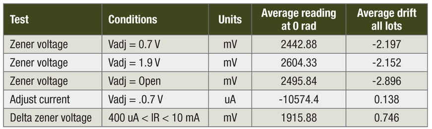
As seen in Figure 1, the 30 krad(Si) LDR Total Ionizing Dose (TID) level, the unbiased sample showed less than 20mV of drift. With a 2.49V average set point, this leads to an error of 0.8 percent (0.02V/2.49V). The ELDRS-free version of the LM136-2.5, irradiated to 100 krad(Si) as referenced in Table 1, leads to a 0.12 percent error (with the Vadj open). Depending on the application, this error may be tolerable.
Table 1: ELDRS-free LM136-2.5 parameter drift with 100 krad(Si) TID at LDR. [2
(Click graphic to zoom by 1.9x)
|
|
]
After characterizing a device at LDR and HDR, assuming the device is not ELDRS-free, the end use should determine whether the part can be used and whether the radiation damage can be accounted for. As many applications for rad-hard devices are within Earth orbit, the effects of LDR damage will usually be of greater concern.
Examine the functional blocks
Coming back to the hybrid level, the greater concern with radiation testing should be at the hybrid level. Just because one component exhibits ELDRS does not mean it will fail in circuit. The real test is whether the hybrid-level parameters meet specifications post-irradiation. In-circuit interactions can counteract LDR degradation, or parameters that were thought to be important may not affect the hybrid level parameters; in the similar but opposite scenario, if ELDRS-free parts are used, a parameter that was thought to be unimportant may become important when the LDR drift does not counteract drift in another part of the circuit.
Going back to the LM136-2.5, one example of its use is in a feedback loop as a reference to generate an error signal via an op-amp. If the op-amp is characterized with TID, one will likely see a distinct direction in input offset voltage (either it will tend to drift positive or negative with TID). With a known input offset voltage drift direction, one can place the LM136-2.5 on the appropriate input, inverting or non-inverting, to counteract both the Zener voltage shift of the reference and the input offset voltage shift of the op-amp (depending on which pin the reference is placed on, an inversion may be necessary somewhere after the initial error signal). This may not perfectly cancel out, depending on the magnitude of the chosen op-amp’s drift, but this compensating technique can reduce what was a 0.8 percent error on the HDR-designed LM136-2.5. Further, if a design were using this HDR-designed LM136-2.5 and switched to the ELDRS-free design in order to meet a customer’s requirements, the error signal would show more drift with TID due to the lack of compensation.
In the previous example, one could use an ELDRS-free reference and an ELDRS-free op-amp to minimize both drifts, but the cost of using these ELDRS-free parts can dramatically increase the cost of the whole hybrid. Purchasing an ELDRS guarantee on a component can boost the cost of a part from several dollars to a few hundred dollars. Further, when a company works to LDR-harden a design, attributes of the original design can be overlooked (e.g. op-amp bandwidth can be overlooked when focusing on offset voltages and bias current hardening). The more elegant solution is available and is lower cost, but many procurers of hybrids do not have free rein to delve into the design to verify the radiation drift; their hands are often tied by requirements dictated to them by their customers.
Evaluate and test before moving to ELDRS-free
In summary, the major design concern should really be at the hybrid or functional block level, not necessarily at the component level. Individual components within a functional block may counteract each other’s radiation effects, or the effects of a component may not cause a large impact on the hybrid-level parameters. Transitioning to ELDRS-free components will add cost without necessarily improving performance. When evaluating whether a hybrid can be used in a low-dose environment, ELDRS-free components should be a guideline rather than a strict rule.
References
[1] S.S. McClure, J.L. Gorelick, C.C. Yui, B.G. Rax, M.C. Wiedeman, “Continuing evaluation of bipolar linear devices for total dose bias dependency and ELDRS effects,” 2003 IEEE Radiation Effects Data Workshop Record, pp. 1-5.
[2] K. Krickmeyer, L. McGee, B. Brown, L. Miller, “Low dose rate test results for National Semiconductor’s ELDRS-free LM136-2.5 bipolar reference,” 2009 IEEE Radiation Effects Data Workshop, pp. 47-50.
Brian Bennett is an Electrical Engineer with Crane Aerospace & Electronics at the Redmond, WA, location, where he also serves as the lead of the Radiation Hardness Assurance group. Brian works in the design and development of Interpoint power converter products for space applications. These products have been used on missions including Mars Science Lab Curiosity, Hubble, Mars Rover, and Cassini, in addition to most military and space satellites. Contact Brian at [email protected].
Crane Aerospace & Electronics 425-882-3100 www.craneae.com/interpoint


