
The inefficiency of the instruction manual: Why 3D animation makes the difference in military embedded systems
StoryFebruary 18, 2009

Jeff Covert
Dassault Systemes
While the stubborn tradition of paper has prevented technical documents from enjoying the savings of the digital age, the move to electronic 3D documents can be quick when the data already exists in your Product Lifecycle Management (PLM) system.
When an embedded system is produced using PLM technology, all the information is available to create multimedia manuals that illustrate how to, for example, remove an RF module from a missile. Leveraging digital assets can reap large benefits in transforming technical documents and eliminating trial and error, streamlining the manufacturing process, and making electronic collaboration more efficient.
How many pages are in the average government document? How large is an F/A 18 ownerís manual? How do you learn to replace a jet engine on the rolling deck of an aircraft carrier
within a two-hour time limit? When a sailor replaces any module, how can it be done with the minimum amount of training, quickly and safely?
Today, the majority of documentation for embedded systems is paper-based. At home, we use online maps and Web search tools instead of telephone directories. Why? Because Google Maps offers a more interesting and compelling multimedia option, and is always up-to-date and user friendly. We use multimedia tools because, at their core, people are visual creatures. For these same reasons, 3D visualization should be leveraged for embedded product development.
However, the benefits extend far beyond the simply visual. 3D animation provides the benefits that, for example, enable a sailor to replace any module with minimum training. Because
the necessary images for a multimedia manual already exist within the design tools, the supporting multimedia changes as the design changes. These images are pulled directly from the embedded systemsí design; they are the design – moving, changing, precisely illustrating what needs to be done.
By creating 3D electronic documents, engineers can more easily demonstrate proper procedures and instructions and reduce trial and error. They also save valuable time by
improving processes and increasing manufacturing effectiveness. At the same time, collaboration throughout an organization is made more efficient.
Transforming technical documentation
Software can animate the 3D PLM drawings in precisely the manner in which the subject operates. For example, what if an avionics module must be replaced in a commercial aircraft? The design software knows how many rotations the hatch handle can turn and the angle of the hatch opening. All the design details support the virtual instructions to remove the unit. Where
should the technician stand, how should the module be removed, what are the steps and tools needed? Annotating the design documents with animation and commentary is much more effective than attempting to describe this process through words and static visuals.
This "eLearning" is optimum when the design details within technical documentation can be animated for and visualized by the technician. Video 1, created using Dassault Systemes' Delmia 3D animation software, shows the accuracy of the 3D approach within its instruction on servicing a jet engine. The focus is not on the beauty of characters, but on the accuracy of the process. The jet engine opens exactly as displayed, showing where the embedded component can be replaced should it fail.
Using this 3D eLearning video, technicians learn how to use a sheet metal stamping machine on parts for electronic assemblies.
Manufacturers using visualization and eLearning print a page or two for prompts and checklists. These reference documents, combined with viewing the executing process on a computer screen, enable one technician to work on a broad collection of modules and aircraft. Companies using 3D documents do not have tables and bookshelves filled with large manuals. When the technician wants to make an annotation to the documents, these notes are kept electronically for real-time updates across organizations and supply chains. Best practices are easily shared across all the work cells. If the embedded system can be field repaired, leveraging PLM data will ensure that proper procedures are used, along with increasing safety and quality and minimizing damage. These documents are very effective when presented to the government for certification testing.
This certification process needs to validate that the approved design matches what was built. When the PLM data is connected and not translated or otherwise modified, the
certifying agency has confidence that the design matches the finished product.
For example, let's say a radar unit has failed and needs to be replaced. A technician is handed the brand new part and a 3-inch binder with the supporting documentation. The
technician reads the applicable section, then opens the box and attempts to replace the unit. There is a loud electrical snap sound as the technician moves a lever to reach the box that needs to come out – oops! (Earlier in the book it states that there is a battery that also needs to be disconnected.) Then the box seems stuck, so the technician gives it a push and it comes out. The new part needs a good push to go back in. If the technician had a 3D animation showing how to do this repair, it would have been safer and faster. The technician also would have learned how to best replace the box. Instead, all the pushing parts together damaged the new unit and the radar still does not work: new part, please. In every aspect, the 3D documents are more efficient and support reusable quality.
Improving the manufacturing process
While manufacturing led the world to total quality and lean processes, the manufacturing process, though lean and automated, is also typically documented on paper. Some of the best manufacturers would argue that paper is fine. However, the comparison is not between paper and software, but between visualizing a process and reading about it. There are some well-documented studies proving that 3D electronic documents improve learning and manufacturing effectiveness.
3D visualization is a leverage point for the mechanical design and electronic circuitry. Embedded systems are largely electronic marvels. A study at the University of Freiburg has validated the eLearning benefits of visualization for electronic circuits.[1] The 3D view and increased understanding derived from seeing the circuitry accelerate learning and product development.
The University of Maryland has conducted studies on the benefits of visualization and virtual manufacturing.[2] One university study was conducted under the USAF Systems Command. One finding was, "Some of the most promising areas (of virtual manufacturing) include manufacturability analysis, validation and evaluation of process plans, partnering in agile enterprises, process design and optimization of production plans and schedules." This study and the data collected and analyzed within it concretely validate the old adage, "A picture is worth a thousand words." It also illustrates the large cost savings possible.
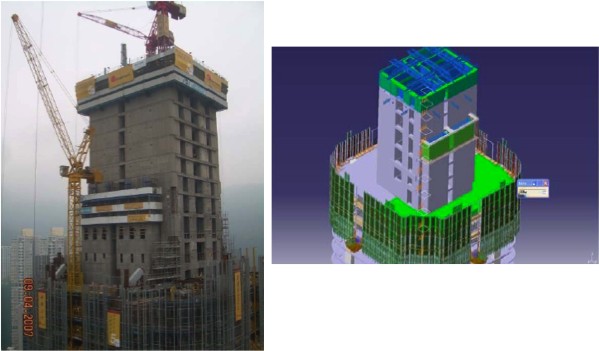
The UMD study provided recommendations for using virtual manufacturing, including part quality, process optimization, and efficient design collaboration. In the business of building systems, the ability to predict how the systems will physically connect and electronically operate is a large step toward lean design and production. This technology also pertains to virtual manufacturing of buildings. For example, Figure 1 depicts a building and the virtual manufacturing image of the same building. Dassault Systemes' Delmia software was used to determine the best sequence to follow to build this structure. The images illustrate that everything that can be built should first be built in the computer. Any less is wasteful.
Figure 1: A building and the virtual manufacturing image of the same building are shown, illustrating that everything that can be built should first be built in the computer.
(Click graphic to zoom by 1.3x)
|
|
In a very similar way, firms can simulate the best manufacturing processes. This is critical in the short-run, high-mix environment of embedded components where line changeovers can be very expensive. Instead of setting up a production line and iterating how to maximize yield and flow, it can be modeled in the computer first. Tools, jigs, and the process are modeled and run at computer speeds until the process is acceptable. Only then do people walk onto the floor and start to assemble the line.
Streamlining electronic collaboration
Electronic collaboration across suppliers is another area where interactive 3D documents and animation can create a new paradigm. Todayís value chain is a latticework of suppliers. The upstream customers and downstream suppliers need to see what the vendor means. In the supplier world, it is not uncommon to hear, "I think they meant Ö" Animating and virtualizing circuitry design processes can dramatically decrease development time and system integration time. Conversely, information that is not clear and not visualized in 3D has the potential to require rework and slow government certification. A collaborative design process runs faster and results in greater quality. Instead of synchronizing and testing at fixed intervals, a subsystem
or its larger system can be virtually and collaboratively built ad hoc. In this global design paradigm, testing and validation constantly occur.
A picture is worth a 1,000 words; moving pictures: 4,000
"Do more with less" has been the military embedded systems mandate for decades. Efficiency is always in style, but when times are tough, wasted time and material are unacceptable. Product Lifecycle Management enables engineers to visualize their dreams while earning award fees (additional "bonus" fees that government prime contractors and frequently subcontractors are paid when budget, quality, or time metrics are surpassed). Additionally, leveraging 3D visualization in documentation maintenance reduces trial and error. It can also streamline the manufacturing and collaboration processes. The resulting time compression will continue making eLearning and 3D visualization the new minimum requirement.
Jeff Covert is the North American vice president for CATIA Mechanical Sales for Dassault Systemes. He is responsible for illustrating the value of virtual product development across many industries. Prior to joining Dassault Systemes, he was a consulting regional vice president at Oracle Corporation. He led core technology consulting for the western United States and consulted on eBusiness strategy and design. Jeff is also an adjunct professor at Loyola Marymount University, teaching in the Graduate School of Business in the executive and part-time
MBA programs. He is also the chairman of the Deanís Advisory Council for the College of Business. Jeff has held management positions with Motorola, Digital Equipment, NCR, and two startups. He received a B.S. from the University of Southern California and an MBA from Loyola Marymount University.
Dassault Systemes
818-673-2213
www.3ds.com
[1] Reeves, Thomas, and Shirley
Yamashita. "World Conference on E-Learning in Corporate, Government,
Healthcare, and Higher Education." Education and information Technology
Library. Oct. 2006. Association for the Advancement of Computing in Education.
11 Nov. 2008
.
[2] Lawrence Associates, Inc. "Manufacturing
Technology Special Advanced Studies." Contribution to Virtual
Manufacturing Background Research, Phase II. 01 Dec. 1995. University of
Maryland. 10 Nov. 2008 .


