
Test and evaluation of advanced radar systems
StorySeptember 10, 2019

Tony Girard
Mercury Systems
Advances in both electronic warfare (EW) and radar systems present numerous challenges in the test and evaluation of these modern systems. Radar capabilities such as synthetic aperture radar (SAR) imaging, multiple degrees of agility, and a wide spectral range – coupled with the introduction of cognitive/adaptive EW jamming techniques – have dramatically increased the complexity and cost of developing effective test environments. Typical Digital Radio Frequency Memory (DRFM)-based target generation can fall short, as many radar systems can quickly recognize DRFM-generated target returns as decoys. Test and evaluation engineers and test equipment providers are attempting to address these challenges by building in general-purpose graphics processing units (GPGPU); live, virtual, and constructive (LVC) simulations; and the next generation of DRFM technologies to provide the necessary capabilities, features, and quality of target and image returns to properly exercise the latest radar systems.
Current challenges in testing advanced radar systems
Whether ground-based, shipboard, or mounted on an aircraft or missile, radar systems are essential components of both the offense and defense of the platforms they are used on. Often considered the “eyes” of the platform, radar systems are used for everything from intelligence gathering, navigation, and traffic control to weather reporting, platform protection, and targeting. Given the criticality of radar performance to the safety and effectivity of the platform, there are two major fronts of advancement.
The first is to continue to increase the capability, capacity, and intelligence of the radar system itself, while the second is to find ways to defeat, deceive, or blind the system, generally referred to as electronic warfare (EW). In order to properly ensure these critical systems are operating as designed in a wide variety of scenarios and possibly under electronic attack, extensive testing and evaluation is essential. Radar system designers and end users have relied on a combination of test equipment and field testing to provide this assurance, but as the systems themselves grow more complex, the requirements on the test equipment grow more daunting.
For example, advances in EW systems have brought increased complexity to the prospect of dominating the electromagnetic spectrum. Expanded frequency ranges, instantaneous bandwidth (IBW), and complex signal coding and other advanced EW systems capabilities result in system performance that is difficult to test and evaluate.
Radar test equipment (RTE) – employed at various stages of the development, test, evaluation, and production cycle – provides a wide variety of simulated radio frequency (RF) returns that exercise radar sensors. These include fire control, surveillance, guidance, imaging, proximity, fuses, and altimeters. There are two primary types of RTE: First is a target generator, a basic system used to generate a single or limited number of targets returns to a radar-under-test. The other is an environment simulator, which is substantially more advanced and generates a number of targets as well as other RF effects like clutter, terrain, weather, and other environmental factors. Environment simulators often include capabilities to simulate electronic countermeasure returns including noncoherent denial and coherent deceptive techniques.
RTE systems are the optimal tool for low-cost radar testing, as they avoid the expense and unpredictability associated with full field trials. RTE is used in a secure, controlled environment, where situational complexity is dialed in as required. With their ability to control the full spectrum of test metrics, RTE delivers excellent results when testing radar development and upgrades and during in-line production, platform integration, repair, and operator training.
The most usable RTE uses Modular Open Systems Architecture (MOSA) hardware as well as flexible and scalable software-defined functionality. This approach to designing RTE hardware and software makes it easily upgradeable as new capabilities are released and as requirements for testing advanced radar capabilities evolve. Figure 1 shows an example of a graphical user interface control display with comprehensive user-defined functionality.
Figure 1 | An example of a radar environment simulator graphical user interface. Courtesy Mercury Systems.
|
|

RTE architectures
RTE employs two basic architectures; synthesizer- and Digital Radio Frequency Memory (DRFM)-based. Synthesizer-based systems do not use the signal generated by the radar as the source return; rather, these systems use frequency synthesizers to create the return independently. A synthesizer-based system requires RTE designers with detailed knowledge of the waveforms used by the radar-under-test in order to generate signal returns that properly match the waveforms generated by the radar. Additionally, in general a synthesizer-based system must be synchronized to the radar-under-test to ensure that the phase relationship of the returns is fixed with respect to the radar to achieve the correct coherent pulse and Doppler processing. Typically, synthesizer-based RTE provides better signal performance in terms of signal-to-noise ratio, spurious-free dynamic range, noise floor, etc. Synthesizer-based systems are well suited for radar systems that do not use complex radar waveforms or signal return processing, or for individual radar systems for which the waveforms are well-known and access to internal radar signals and data is not an issue.
In contrast, DRFM-based systems use the waveform generated by the radar-under-test as the source for the signal return. These systems typically digitize RF waveforms generated by the radar-under-test, store the waveforms, apply the appropriate signal modulation, and then play the RF waveforms back to the radar to generate the return. Since the return signal is DRFM-based, the RTE system designer or user needs no detailed knowledge of the radar-under-test to generate useful returns. DRFM-based systems have the benefit of being able to respond on a pulse-by-pulse basis to radar waveform agility in terms of frequency, pulse width, and separation. In addition, they dynamically respond to changes in radar signal modulation. While a priori radar waveform information is not necessary for DRFM-based systems, the frequency range and IBW of the RTE is set by the system design. It’s important to note the signal performance of DRFM-based RTE is limited by the resolution and sample rate of the analog-to-digital converters (ADC) and digital-to-analog converters (DAC) used in the system. Although it is possible to increase IBW by increasing ADC/DAC sample rates, doing so reduces ADC/DAC resolution, which in turn reduces signal performance. IBW versus signal performance is a trade-off decision that must be made by the RTE system designer.
Designers must also consider another significant aspect of DRFM-based RTE: Over the last 30-plus years, DRFM technology has been increasingly used in ECM jammer systems to deny and/or deceive radar systems. As a result, modern radar systems have developed methods to quickly detect “synthetic” DRFM-generated signals and identify them as jamming signals rather than tracking them as valid targets. DRFM-based RTE designers must continue to adopt new capabilities to counter this trend in order for this approach to remain a viable option for testing advanced radar equipment. This requires the development of innovative hardware with higher fidelity and greater agility than historically deployed.
Test configurations affect results
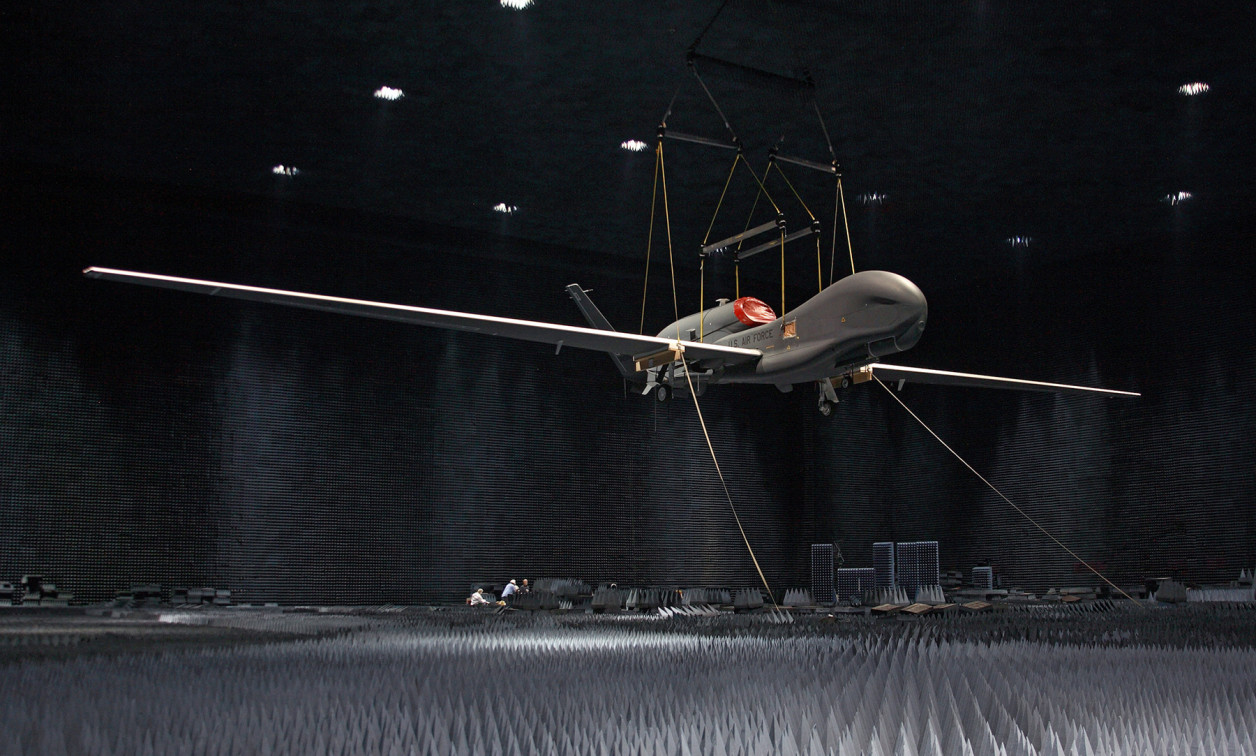
Decisions on how best to test and evaluate a new radar system requires consideration of both the type of system under test as well as the testing configuration. RTE systems have two basic configurations, free-space and direct-inject, with options for a hybrid approach. Free-space RTE is completely external to the radar-under-test and receives the radar signal from a “free-space” antenna, then radiates the return to the radar through the same or a similar antenna. One way of testing is by placing the system under test suspended in an anechoic chamber and the RTE colocated, but not directly connected to, the radar. (See lead photo.) If the radar has a directional beam that is not received by the free-space antenna, no return can be generated. RTE with an IBW narrower than the frequency agility of the radar must have the ability to measure the radar frequency quickly and tune the system’s IBW accordingly. A free-space system has the advantage of needing no knowledge of or physical connection to the radar-under-test. The disadvantage is that free-space systems only generate returns on the radial in which the antenna is positioned. That said, a free-space system remains a good choice when “opening” the radar for signal access is undesirable or impossible, and when providing RF returns from the RTE antenna radial is acceptable.
When access to the radar signal is not an issue, it is possible to inject the radar transmit signal directly into the RTE system rather than through an antenna. Because the direct-inject system receives the signal from a point before the antenna, the RTE receives every radar pulse, regardless of the antenna’s pointing angle. However, direct-inject systems require azimuth and elevation information from the radar in order to selectively generate radar returns for a target only when that target is within the beam width of the radar’s pointing angle.
Additionally, for the RTE to generate the desired RF scene, it requires other information from the radar-under-test, such as antenna patterns. While direct-inject RTE is more complex and has the disadvantage of requiring connection to radar RF signals and data buses, it provides the distinct advantage of generating returns with six degrees of freedom to a system under test. Essentially, this covers the entire radar target space. A direct-inject system is a good choice when full-scene generation is desired, access to internal radar signal is possible, and detailed characterization of the radar’s antenna is not a concern.
Radar modalities add complexity
The features and functions of RTE used with air-to-air and surface-to-air radars are similar, yet they have subtle differences in terms of background clutter modeling and multipath returns. The more significant variance is in RTE for air-to-ground radar, which brings the additional challenge of emulating complex signal modulations required for SAR; such signal returns require RTE to combine modulation for many individual point returns, or pixels, in order to provide high-fidelity distributed images in the RF return. Historically, simulated SAR returns were generated with a time-domain approach that employs what’s called a delay tap for each downrange pixel. Each pixel is modulated with unique coefficients for crossrange effects based on the desired image, and then summed (Figure 2) to produce a complete SAR RF signal return. While hardware-intensive, this approach requires no prior knowledge of the RF waveform. In addition, low system-insertion delays provide images relatively close to the radar.
Figure 2 | Time-domain SAR scene generation logic.
|
|

RTE systems that produce SAR returns by processing the RF signal based on a convolution in the frequency domain (Figure 3) have advantages over time-domain processing. Frequency-domain systems provide higher-resolution images both downrange and crossrange with significantly less signal processing hardware compared to time-domain processing systems.
Figure 3 | Frequency-domain SAR scene generation approach.
|
|

Using efficient multi-GPU servers with optimized software for signal modulation coefficient calculations, high-resolution SAR images can be calculated in near-real time.
More complexity means more data
Many radar test and evaluation applications need to store captured radar waveforms and signals transmitted to the radar, with the data enabling the radar engineer to evaluate the performance of the radar transmissions and the radar’s algorithm response to target and/or jamming returns. Any time defense-related radar signal and processing data is stored, information assurance should be seriously considered with respect to protecting sensitive radar parameters. As radar bandwidths increase, storing the real-time data with the necessary levels of protection becomes an increasingly complex challenge. Many of today’s RTE systems use mass data storage/retrieval capability, but few offer validated information-assurance features.
Future challenges
Complex, coordinated, and multidomain EW scenarios continue to drive the need to support wider analog bandwidths and ever-higher-fidelity signal capture and generation. This in turn requires ADC/DAC technology with cutting-edge sample rate and resolution capabilities. For example, devices that combine multiple ADC/DAC devices packaged with FPGA resources, such as the new wave of RF system-on-chip (RFSoC) products, allow RF channelized architectures to be utilized within reasonable size and cost constraints. RF channelization reduces the need for costly fast-tuning RF conversion stages to cover wide frequency ranges. As this technology develops, direct digital conversion of radar RF signals becomes possible, reducing or possibly eliminating the need for RF to IF conversion. This move in turn reduces cost and improves performance. Additionally, the move toward multicore GPU servers for complex radar signals will accelerate as machine learning and artificial intelligence are employed in radar and jammer systems to enable cognitive/adaptive capabilities.
As advances in technology improve radar system performance, agility, and built-in electronic protection capabilities, RTE functionality must keep pace. Designing MOSA-based RTE architectures with the latest secure digital processing hardware and software configurable features are keys to supporting the future needs of the radar and EW test and evaluation community.
Tony Girard is Chief Technologist for Mercury Defense Systems, based in Cypress, California. Mr. Girard has 25-plus years architecting complex EW training, test, and evaluation solutions for a variety of RF applications including radar, EA, and SIGINT systems for airborne, surface, and laboratory applications. He has a bachelor’s degree in electrical engineering from California State Polytechnic University.
Mercury Systems
www.mrcy.com


