
Radar and electronic warfare system modeling
StoryNovember 13, 2018


Active electronically steered phased array (AESA) systems provide the technology platform for multifunction radio-frequency (RF) systems. Today?s systems can include a combination of radar, electronic warfare (EW), and communications functionality within the same physical system using a common antenna array front end. To reduce the risk of system errors and overcome challenging interference sources, system modeling techniques can be used to design a system before any equipment is developed. These techniques can also be used for analysis during the up-front requirements phase of a program. The same types of systems can also be used to model an adversary?s system capability.
Let’s examine models for simulating an EW and radar scenario. To build the scenario model, we start with the phased-array antenna design and show some of the parameters in the system model that can be updated on a pulse-by-pulse basis, including waveform selection, frequency agility, and pulse repetition frequency (PRF). With a phased-array front end, beamforming and direction-of-arrival (DOA) estimation can be used to improve operations in an interference-rich environment. The ability to change key system parameters enables a dynamic, closed-loop model between detections and scheduling.
AESA systems offer system-level flexibility
AESA systems provide spatial information in the field of view without physically moving the antenna. By electronically steering beams, system-level flexibility is possible on a pulse-by-pulse basis. Mode and beam patterns can be changed much more quickly than with mechanically steered arrays. In addition, beam-pattern flexibility is greatly enhanced by applying digital and RF weighting to control where the system looks and listens. System resources in a multifunction system can be used to transmit and receive radar and communications signals, while other processing intervals can be dedicated to listen for emissions from other sources.
Modeled using MATLAB and Simulink, the examples described below are based on a monostatic X-band radar system. The radar receiver for this system can also function as an EW receiver. The RF front end is designed as a 64-element (8 x 8) phased array.
Figure 1 shows a uniform rectangular array (URA) that is typical in a phased-array system. The figure also shows the corresponding beam pattern with weighting applied to the elements to reduce side lobe levels (away from the main beam).
 |
|
|
(Click graphic to zoom) |
Antenna elements designed specifically for EW applications can also be used within the antenna array to improve the model fidelity. Figure 2 shows the 3D directivity pattern for an individual element designed using a cavity-backed spiral, an antenna element that is commonly used in EW applications for improved direction-of-arrival performance.
 |
|
|
(Click graphic to zoom) |
With a two-dimensional array, spatial signal processing algorithms including direction-of-arrival and beamforming can be implemented without having to mechanically steer the physical array. The examples below demonstrate how these techniques can be leveraged in the system scenario.
Multifunction system parameters: Frequency, waveform, and PRF
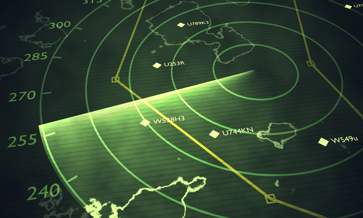
Radar and EW systems that perform multiple functions require flexibility in waveform generation and processing, frequency of operation, and pulse repetition frequency. Figure 3 illustrates two aircraft approaching a radar, in which the aircraft are located at different distances. Waveforms and PRFs are selected based on what the radar or EW sensor detects.
 |
|
|
(Click graphic to zoom) |
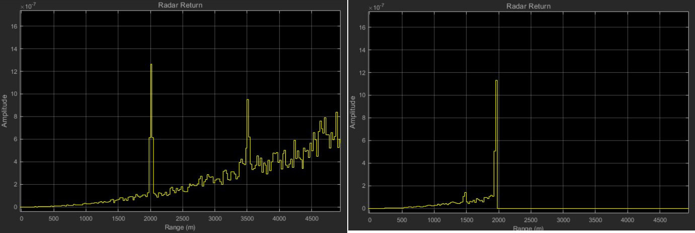
The plots in Figure 4 show two targets that are in coverage in the scope on the left. During this time, the targets are far away from the system, so a search waveform at a lower PRF is used. In this case, free system resources can be allocated to other tasks such as searching additional sectors. As the closer target continues its approach, a threshold is crossed (in this case 2 km), and the waveform selection shifts to a track waveform at a much higher PRF. Less energy is available to be used on the target further away, as well as for other functions.
 |
|
|
(Click graphic to zoom) |
In addition to system parameters, multifunction systems also switch between modes and operational mission types. The next example includes both radar and EW operations.
Intelligent nulling to remove interference sources
In Figure 3, the two aircraft approaching the radar are targets that appear as detections to the radar. When a radar system is monitoring a region of airspace, and the jammer and target are not located within a receive beam, the AESA beam steering capabilities can be used to resolve targets in range and angle. In the scene shown in Figure 5, the target and jammer are separated by many beam-width multiples.
 |
|
|
(Click graphic to zoom) |
Here, the fixed-location monostatic radar can detect and track the target aircraft. Now the second aircraft enters the field of view and generates an interference signal that will confuse the radar. The radar can use some of its processing intervals to listen to the RF environment. As part of this operation, the interference source can be detected. In addition to detection, the phased-array channels can be used to determine an angle in both azimuth and elevation for where the jammer is located.
This information can be used to generate a beam pattern that ensures a null is placed in the same direction of the interference source (40 degrees off the radar boresight in this example). This pattern serves the following two purposes: First, to reduce the effects of the jammer; and second, to strengthen the return of the desired signal coming from the original target. Figure 6 shows the resulting nulling pattern that can be used to reduce the effect of the jammer.
 |
|
|
(Click graphic to zoom) |
Frequency agility techniques to remove interference
In cases where the jammer and target aircraft are very close to each other in the radar field of view, it may not be possible to eliminate the interface source without also eliminating the desired target. A simple scenario is shown in Figure 7.
 |
|
|
(Click graphic to zoom) |
[Figure 7 | .]
For this case, frequency agility techniques enable the radar to avoid the interference generated by a jammer. Figure 8 shows a system model in which jammer interference can be enabled or disabled. The waveform generation can be operated on multiple bands to simulate frequency-hopping.
 |
|
|
(Click graphic to zoom) |
In this example, the target can determine the signal characteristics transmitted from the radar. The target aircraft can use this information to generate its own transmit pulse with the intent to confuse the radar receiver. That is, the target generates a jamming signal using the same signal characteristics to make it appear to the radar that there are multiple targets.
The signal-processing blocks in Figure 9 show paths for each frequency band, including the original band and the band that is used in the presence of interference.
 |
|
|
(Click graphic to zoom) |
In Figure 10, note that at baseband, we start with a single target (left-most plot). When the jammer sends its signal, we see multiple targets (middle plot). For both cases, band 2 does not contain any detected signals.
As frequency-hopping is applied, we see in the right plot of Figure 10 how the interference and radar signals show up in different bands. This example can also be extended to a much more complicated frequency-hopping scheme.
 |
|
|
(Click graphic to zoom) |
Building flexible models
Multifunction systems used for radar, EW, and communications are very complex: System parameters change on the fly and modes change on a pulse basis. Signal-processing and scheduling systems work in a closed loop, in which it is easy to make design errors. Models can be built to represent scenarios of a range of complexity; these models reduce risk, prove out difficult concepts, and improve all phases of the acquisition and development cycle
Honglei Chen is a principal engineer at MathWorks where he leads the development of phased-array system simulation. He received his Bachelor of Science from Beijing Institute of Technology and his MS and PhD, both in electrical engineering, from the University of Massachusetts Dartmouth. Rob Graessle is a Senior Application Engineer at MathWorks focused on the aerospace and defense industry. He previously worked for the Air Force Research Laboratory, Sensors Directorate, and holds a BS and MS from Miami University. Rick Gentile is a product manager at MathWorks where he is focused on tools to help develop phased-array radar, EW, and communication systems. Prior to joining MathWorks, Rick was a radar-systems engineer at MITRE and MIT Lincoln Laboratory, where he worked on the development of many large radar systems.
MathWorks • www.mathworks.com
Figure 1: Array geometry (1a) and corresponding beam pattern (1b). Image: The MathWorks.
Figure 2: Directivity pattern (2a) and antenna element (2b) for a cavity-backed spiral. Image: The MathWorks.
Figure 3: Scenario with two aircraft approaching a surveillance radar. Image: The MathWorks.
Figure 4: PRF plots showing agility based on target locations. Image: The MathWorks.
Figure 5: Scenario with two aircraft approaching surveillance radar separated in angle. Image: The MathWorks.
Figure 6: Null added in beam pattern to remove interference source. Image: The MathWorks.
Figure 7: Scenario with two aircraft located close to each other approaching surveillance radar. Image: The MathWorks.
Figure 8: Radar and EW system model. Image: The MathWorks.
Figure 9: Radar and EW signal-processing model. Image: The MathWorks.
Figure 10: Plots of processed results for system scenario. Image: The MathWorks.


