
Mitigating undesired input beat frequencies in parallel DC-DC converter arrays
StoryFebruary 20, 2012


When an array of switching DC-DC converters is connected in parallel for higher power output, differences in operating frequencies result in undesired beat frequencies at the common input bus. The result is an unwanted increase in AC ripple currents circulating in the input sections of the converters. By using simple input filtering, the AC input ripple current can be significantly curtailed. DC-DC converters with higher fundamental switching frequencies (>1 MHz) permit the use of smaller filtering components, suiting systems where overall space and weight are at a premium.
While a single DC-DC converter is often a preferable solution, there are many instances when two or more converters are needed to meet a military system’s power capacity requirements. In such applications, an array of two or more DC-DC converters may be connected in parallel to generate the requisite power – and in other cases where an application needs to be robust, fault-tolerant or N+1 redundant power supplies are used to meet the capacity requirements.
In critical military applications where power supply failure can be catastrophic, fault-tolerant power supplies use N+1 similar converters to provide a very high level of reliability. Through redundancy, fault-tolerant systems ensure that there is at least one more module than the minimum required to carry the load in case of converter failure.
If the DC-DC converters in an array are operating off the same feed, they are typically collocated to gain the benefit of shared thermal and shielding features, while saving real estate. Although these converters may be of the same type, switching frequency mismatches will occur unless the DC-DC converters selected permit synchronization.
Because of slight variations or mismatches in nonsynchronous DC-DC converters operating in parallel off the same input bus voltage, there are small differences in operating frequencies of these converters. This difference in converter operating frequencies results in undesired beat frequencies in the input current to the array. As a result, the AC ripple current circulating in the input section of the converters is increased. While converters offering a synchronization method do avoid beat frequencies as there are no operating frequency mismatches, the choice of selecting converters off-the-shelf is restricted, which can lead to lower overall system efficiency and power density. By implementing simple input filters, the input ripple currents of an array of unsynchronized converters can be easily suppressed significantly, along with beat frequency components, allowing unsynchronized converters to be considered.
Beat frequencies in parallel arrays of DC-DC converters
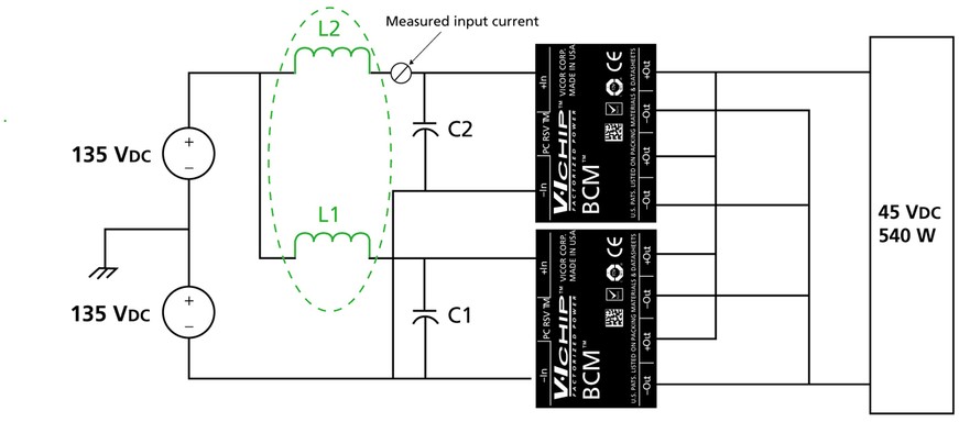
To demonstrate this problem and the impact of input filtering, let us take a look at military power systems such as RF transmitters or microwave radio links, which require substantial power. For example, a system requiring 2.1 kW output power from a MIL-STD-704E supply connects eight 270 W bus converters in parallel to form a high-power DC-DC array. For simplicity, a scaled-down version – an array of two high-input voltage 270 W sine amplitude bus converters in parallel, providing a total output power of 540 W – will be used for measurement (Figure 1).
Figure 1: An array of two high-input voltage 270 W DC-DC converters in parallel with subsequent input filter inductors, L1 and L2, shown in green.
(Click graphic to zoom by 1.9x)
|
|
Even though sine amplitude bus converters switch at fixed multi-MHz frequencies, part-to-part variations in members of this family result in each converter in the array operating at a slightly different switching frequency. The interaction between the switching noise of each DC-DC converter in the array creates the undesired beat frequencies, at multiples of the differences between the operating frequencies of the converters.
The impact of the undesired beat frequency is most notable in the ripple current circulating amongst the DC-DC converters of the array. The ripple currents of the switching frequencies add up to generate an amplitude modulation of the overall ripple current envelope of the converters. For instance, in the parallel DC-DC converter array described earlier and test setup depicted in Figure 1, a pair of interconnected bus converters with nominal switching frequency of 1.7 MHz might have actual switching frequencies of f1=1700 kHz, and f2=1702.7 kHz. The 2.7 kHz difference between the two means that the total input current will have a much lower frequency component to the apparent ripple.
During periods of time when the ripple amplitudes are highest, the copper losses in the interconnects wiring between the two converters in question are higher than they need to be: The circulating AC ripple current is not being used by the DC-DCs, but it is still flowing through conductors with finite resistance. High additive ripple currents can stress input bypassing capacitors as well, and system noise can be increased, depending on the board layout. In some cases these circulating currents can constructively interfere with sufficient amplitude to lead to an unpredictable behavior of the converters themselves, for example, erroneous detection of an overcurrent condition inside a module.
To practically demonstrate the problem of increased input ripple current and generation of low beat frequency components, a pair of high-voltage 270 W BCM bus converters is connected as a simple parallel array, as shown in Figure 2. For the initial measurement, the input inductors L1 and L2 are not included and there is no input filtering beyond the input bypass capacitors C1 and C2. Because of asynchronous switching of two modules in the array, the AC input ripple current frequencies are also different. With a common input and no inductive filtering, the AC ripple currents mix and generate ripple with modulated amplitude based on the lower beat frequency as discussed previously.
This array was built from two bus converters operating at 270 VIN and 45 VOUT. The nominal fundamental operating frequency for this converter model is 1.7 MHz, and again to start with, the filtering inductors shown in Figure 1 were not in the circuit. The input ripple current to one of the modules, shown in Figure 1, was measured. The time domain plot of the resulting performance is shown in Figure 2(a). For the bus converter array used in this measurement, the total input current was about 2.1 ADC for full-load operation.
Figure 2: The time domain scope plot (2a) shows that ripple current without the filter inductors is high (844 mA peak-to-peak). Plot (2b) shows ripple current is substantially curtailed (143 mA peak-to-peak) with filter inductors.
(Click graphic to zoom by 1.9x)
|
|

Suppressing the beats
With fairly simple input filtering, the unwanted AC ripple currents circulating between unsynchronized converters in an array can be easily controlled. The input inductors, labeled L1 and L2 in Figure 1 are incorporated to serve as additional input filters. In this experimental setup, the inductors were 0.4 µH, and were placed in series with the +In leg of each bus converter in the array. The input inductors increase the impedance between the input stage of one converter and the other converters in the array at the switching frequency. In this case, the impedance of the inductors is roughly 4 Ω at the 1.7 MHz fundamental switching frequency of the bus converters. This impedance reduces the high frequency AC circulating currents in the system.
The resulting performance after the input inductors were added is shown in Figure 2(b).
The overall ripple amplitude is significantly reduced, with a corresponding reduction in the lower frequency modulation of the ripple current envelope. As a result, with input filter inductors, the amplitude of the input ripple current drops from 844 mA peak-to-peak to below 143 mA peak-to-peak.
Hence, it was observed that the circulating AC ripple current at the input of an array of nonsynchronized DC-DC converters can be substantially higher if no filtering is employed at the common input bus of this array of parallel converters. In fact, the AC ripple current can be substantial compared to the DC input current. However, by using simple input filtering, the AC input ripple can be significantly curtailed. Because V•IChip converters used in this example operate at higher fundamental switching frequencies (>1 MHz), smaller filtering components with lower losses were employed, compared to those required for lower switching frequency converters. This can be advantageous for systems where overall space, weight, and efficiency are at a premium.
Input filtering tames AC input ripple current
From the results depicted in Figure 2, it is obvious that input filtering plays an important role in significantly curbing the influence of beat frequencies in an array of switching DC-DC converters connected in parallel. Using simple input filter inductors, it is seen that the amplitude of the AC input ripple current in one of the bus converter modules – in an array of two high-input voltage 270 W DC-DC bus converters – was reduced by more than 80 percent.
Kai Johnstad is Sr. Product Marketing Manager, Transportation, Aerospace, and Defense Products, Vicor Corporation in Andover, Massachusetts, USA. Kai has more than 15 years of experience in the power electronics industry with 8 years in various product marketing roles for Vicor. He holds a BS in Engineering from the University of Illinois at Urbana-Champaign and an MBA from the University of San Francisco. Contact him at [email protected].
Vicor Corporation 800-735-6200 www.vicorpower.com


