Bandwidth is king in aerospace and defense applications
StoryJanuary 29, 2016

Ian Beavers
Analog Devices

Wider frequency communication bands require not only a larger observed bandwidth from a system analog-to-digital converter (ADC), but can also push the need for a higher full-power bandwidth. In some applications, such as electronic warfare (EW) and active phased-array radar, this can require the use of a higher order Nyquist rate band. Next-generation gigasamples per second (GSPS) ADCs allow GHz sampling well into the 3rd and 4th Nyquist band with decimation options to get the dynamic range benefits of oversampling. If an ADC's input bandwidth is high enough, it is possible to downconvert directly in the ADC by undersampling the infrared (IF) signal of interest. Higher-bandwidth input signals and sample rates enable direct RF sampling of wider band signals and possible reduction of an entire stage in a signal chain for lower system power and simplicity.
ADC undersampling is essentially the technique of using a sampling frequency that is less than twice the maximum frequency component in the signal. This technique can also be referred to as harmonic sampling, band pass sampling, or super-Nyquist sampling. To reconstruct the original signal perfectly from the sampled version, the Nyquist-Shannon Sampling theorem indicates that the sample rate must be twice the signal bandwidth of interest. This technique should not be mistaken with a sample rate that is twice the maximum IF frequency component.
If BW is the signal bandwidth of interest, then a sample frequency of Fs > 2BW is required. The signal bandwidth of interest can be between DC to BW or from A to B where BW = A – B. As long as the bandwidth of interest does not overlap an ADC’s Nyquist band, which is half the sample rate (Fs), undersampling can work for higher signal bands with ADCs that have a high full- power bandwidth (FPBW) relative to their respective sample rate (Figure 1).
Figure 1: Wide ADC full-power bandwidth enables the use of higher order Nyquist bands. Band pass filtering of the unused Nyquist zones is mandatory to remove unwanted signal energy that could potentially fold back into the first Nyquist, thereby impacting dynamic range.
(Click graphic to zoom by 1.9x)
|
|

Secrecy is an important aspect of military operations. To reduce the probability of intercept or detection, a radar transmission’s form and magnitude is designed in many cases to spread energy over the widest possible frequency range. Low Probability of Intercept (LPI) and Low Probability of Detection (LPD) are classes of radar systems that possess certain performance characteristics that make them nearly undetectable by today’s modern intercept receivers. LPI features prevent the radar from tripping alarm systems or passive radar-detection equipment.
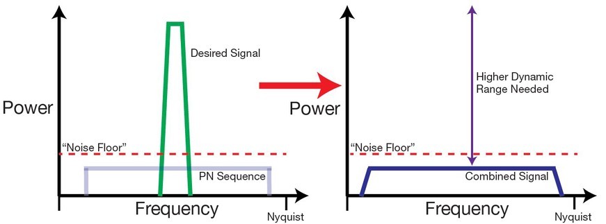
To provide resistance to jamming, systems can be architected by intelligently randomizing and spreading the radar pulses over a wide band so there will only be a very small signal on any one band, an approach known as Direct Sequence Spread Spectrum (DS-SS), as seen in Figure 2. Frequency Hop Spread Spectrum (FH-SS) also provides some protection against full band jamming. In these cases, the wide transmission signal consumes bandwidth that is in excess of what is actually needed for the raw signal of interest. Therefore, a wider receiver bandwidth is needed to continue to advance system capability.
Figure 2: Direct Sequence Spread Spectrum systems require a wide receiver bandwidth and high dynamic range as the signal band of interest is combined with pseudorandom noise (PN) to push the communication into the noise floor.
(Click graphic to zoom by 1.9x)
|
|
One of the most important factors for success in an LPI system is to use the widest signal transmission bandwidth possible to disguise complex waveforms as noise. This technique conversely provides a higher-order challenge for intercept receiver systems that seek to detect and decipher these wideband signals. Therefore, while LPI and LPD are improved, radar transceiver complexity is increased by mandating a system that can capture the entire transmission bandwidth at once. The ability of an ADC to simultaneously digitize 500 MHz, 1,000 MHz, and even larger chunks of spectrum bandwidth in a single Nyquist band helps provide a means to tackle this system challenge. Moving these bands higher in frequency beyond the first Nyquist of the ADC can be even more valuable.
Today’s wideband ADCs offer systems potential for multiple wide Nyquist bands within an undersampling mode of operation. However, using a high order ADC Nyquist band to sample requires strict front-end anti-alias filtering and frequency planning to preventing spectral energy from leaking into other Nyquist zones. It also ensures that unwanted harmonics and other lower frequency signals do not fall into the band of interest after it is folded down to the first Nyquist. The bandpass filter (BPF) upstream of the ADC must been designed to filter out unwanted signals and noise that are not near the nominal bandwidth of interest.
Since a direct sampling technique folds the signal energy from each zone back into the first Nyquist, there is no way to accurately discriminate the source of the content. As a result, rogue energy can appear in the first Nyquist zone, which will degrade signal-to-noise ratio (SNR) and spurious free dynamic range (SFDR). Spectral issues can potentially plague government and military applications, both for sensing and communications.
Digital radio transceivers for military communications are another example of the use of high-speed ADCs and digital-to-analog converters (DACs) that can potentially replace a traditional baseband mixer stage. The architecture has several advantages because tight filtering and adjacent channel rejection can be done in the digital domain for the baseband conversion.
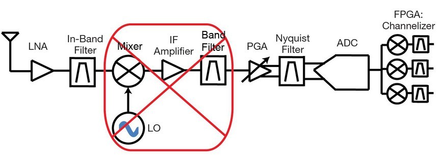
Several advantages are offered by direct RF sampling for radar RF front end designs. First and foremost, it can allow component count reduction, as shown in Figure 3, when an entire downconversion stage can be eliminated. It also removes the need to design a mixing chip to fit a uniquely tailored frequency plan. Second, it can simplify the design of next generation receivers for future signal bandwidths that become available as radar systems are modernized and updated. All that may be needed to work with a new carrier frequency is to select an appropriate sampling rate and incorporate an appropriate band pass filter. Third, it is possible to make a single RF front end suitable for multiple frequency bands. This approach to multifrequency radar receiver front end design eliminates the need for multiple front ends.
Figure 3: The undersampling technique can potentially remove a downconversion stage as the higher input frequency band is given directly to the RF sampling ADC.
(Click graphic to zoom by 1.9x)
|
|
Current generation ADCs now offer a plurality of internal digital down conversion (DDC) processing blocks. Each DDC can apply its own decimation rate and numerically controlled oscillator for tuning placement within a Nyquist band. Processing gain can be achieved within a narrower bandwidth that digitally filters out-of-band noise. This reduces the required ADC output data and minimizes processing complexity in FPGAs and DSPs. However, additional channelizer signal processing can also be done downstream of the ADC.
Wideband communications and sensing systems require extremely high-speed data converters. GSPS ADCs from Analog such as the AD9234, AD9680, and AD9625 not only offer high sample rates for a wider instantaneous bandwidth, but also the ability to sample high frequency inputs above the first Nyquist. A single direct RF-sampling ADC used at a high bandwidth can potentially replace an entire IF-sampling or zero IF-sampling subsystem of mixers, local oscillator (LO) synthesizers, amplifiers, and filters while achieving greater flexibility. This setup can significantly reduce the system’s bill-of-materials (BOM) cost, design time, board size, weight, and power consumption.
Ian Beavers is an applications engineer for the High Speed A/D Converters team at Analog Devices in Greensboro, North Carolina; he has worked for the company since 1999. Ian has more than 20 years of experience in the semiconductor industry and earned a bachelor’s degree in Electrical Engineering from North Carolina State University and an MBA from the University of North Carolina at Greensboro. Readers can contact the author at IanB on Analog Devices’ EngineerZone Online Technical Support Community.
Analog Devices www.analog.com