
ARINC 818 tackles tough sensor fusion issues
StoryMarch 20, 2009

Jon Alexander
Great River Technology

Sensor fusion systems continue to proliferate in military applications like surveillance, target tracking, and missile defense, but they bring their share of system-level challenges such as sensor synchronization, cabling weight, distance restrictions, and EMI. The authors discuss how ARINC 818 (Avionics Digital Video Bus) can be used as a flexible sensor interface to solve these system-level issues. Additionally, a bidirectional ARINC 818 system architecture scheme for time multiplexing multiple sensors onto a single fiber and implementing a return-path for sensor command and control is described.
As sensor fusion systems proliferate in applications like enhanced vision, surveillance, target tracking, and missile defense, many system-level challenges exist when processing is executed remotely from the sensor pod including: sensor synchronization, cabling weight, distance restrictions, and EMI. The ARINC 818 protocol, which has been used extensively in aerospace video systems such as cockpit displays, can be used as a flexible sensor interface to solve these system-level issues. A bidirectional ARINC 818 system architecture is described including a scheme for time multiplexing multiple sensors onto a single fiber and implementing a return path for sensor command and control.
Overview of ARINC 818 protocol
ARINC 818 is relatively new, and many engineers are not yet familiar with the protocol. Before describing how to use ARINC 818 in sensor fusion systems, an overview of the protocol will aid the discussion.
The standard, titled Avionics Digital Video Bus (ADVB), is based on the Fibre Channel Audio Video (FC-AV) standard and is an adaptation of Fibre Channel that adds video transport capabilities. But where the FC-AV standard intends to support a very broad set of industries and applications, ADVB focuses on the critical needs of avionics video. ADVB is simplified from FC-AV with no requirements for link initialization, flow control, or other Fibre Channel exchanges such as port login. ADVB is defined as a unidirectional link, and although simplified, ADVB retains attributes of Fibre Channel that are beneficial for mission-critical video applications, such as high speed, high reliability, low latency, and flexibility.
Additionally, ARINC 818 is a point-to-point, 8B/10B encoded protocol for serial transmission of video and data. The protocol is packetized, video-centric, and very flexible, supporting an array of complex video implementations including the multiplexing of several video streams onto a single link. ARINC 818 and FC-AV define link speeds from 1 Gbps to 8 Gbps with a bandwidth up to 800 MBps, which accommodates the most demanding sensor-fusion applications.
ADVB packet structure
The ADVB frame shown in Figure 1 is ARINC 818's basic transport mechanism. It is important to refer to these packets as "ADVB frames" rather than simply as "frames," to eliminate potential confusion with video frames.
Figure 1: The ADVB frame is the basic transport mechanism for ARINC 818.
(Click graphic to zoom by 1.3x)
|
|
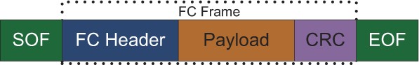
The start of an ADVB frame is signaled by a Start-Of-Frame (SOF) 4-byte ordered set and terminated with an End-Of-Frame (EOF) ordered set. Every ADVB frame has a standard Fibre Channel header comprised of six 32-bit words. These header words pertain to such things as ADVB frame origin and intended destination and ADVB frame position within the sequence. The Source ID (SID) field in the ADVB frame header allows video from each sensor to be distinguished from the other sensors.
The "payload" contains either video, video parameters, or ancillary data. The payload can vary in size but is limited to 2,112 bytes per ADVB frame. To ensure data integrity, all ADVB frames have a 32-bit Cyclic Redundancy Check (CRC) calculated for data between the SOF and the CRC word. The CRC is the same 32-bit polynomial calculation defined for Fibre Channel.
ADVB container structure
The ARINC 818 specification defines a "container" as a set of ADVB frames used to transport video. In other words, a video image and data are encapsulated into a "container" that spans many ADVB frames. The "payload" of each ADVB frame contains either data or video. Within a container, ARINC 818 defines "objects" that contain certain types of data. That is, certain ADVB frames within the container are part of an object. The four types of objects found within a container are shown in Table 1.
Table 1: ADVB frames within the container are part of an object, and four types of objects are found within a container.
(Click graphic to zoom by 1.8x)
|
|
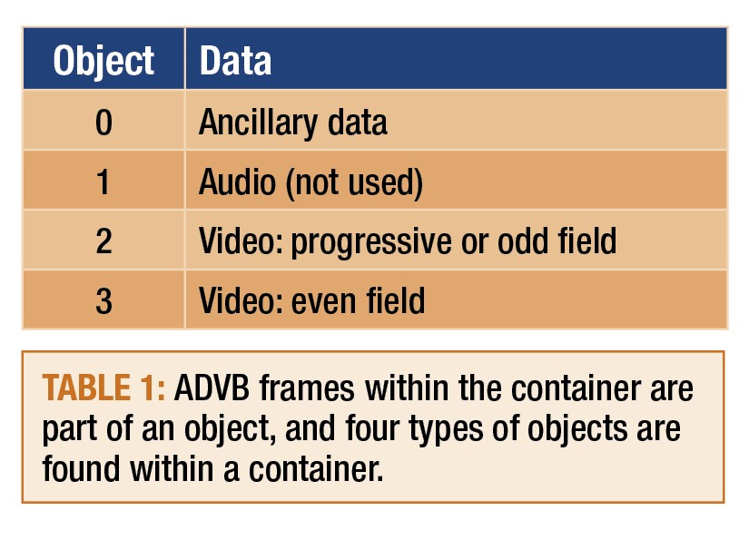
In most cases, a single container maps exactly to a single video frame. An example will clarify how video is transported: To transport an XGA video frame (1,024 x 768, 24-bit color), ARINC 818 will use a total of 1,537 ADVB frames. The payload of the first ADVB frame holds container header information and ancillary data; this will be followed by 1,536 ADVB frames, where the payload of each ADVB frame holds half a line of video.
ARINC 818 sensor fusion interface architecture
Figure 2 shows an architecture for interfacing with three sensors. A sensor interface module, colocated with the sensors, is used to time multiplex video from three sensors onto a single ADVB link. In this example, there are two IR sensors, each with 14 bits per pixel and 640 x 512 resolution at 60 Hz and a 1,024 x 768, 24-bit color optical sensor. Together, these sensors require 220 MBps of throughput and can be multiplexed onto a single 3.1875 Gbps ARINC 818 link.
Figure 2: A sensor interface module, colocated with the sensors, is used to time multiplex video from three sensors onto a single ADVB link.
(Click graphic to zoom by 1.9x)
|
|
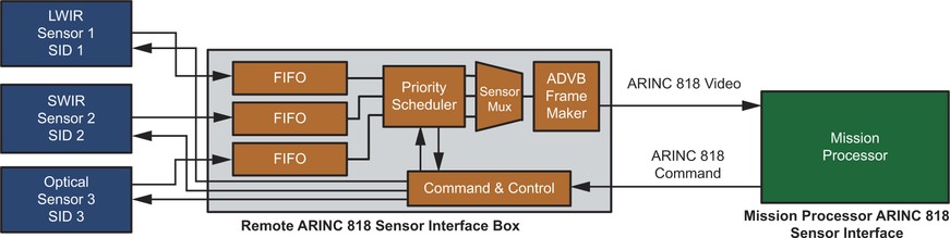
The architecture includes an ARINC 818 command and control path from the receiver. In the example, the command and control path is shown as ARINC 818, but it could be achieved with an RS-422 or similar data bus if a high-speed bus like ARINC 818 isn't required. In this example, ARINC 818 (3.187 Gbps) is more than 300 times faster than RS-422 (10 Mbps).
The sensors may also have ARINC 818 interfaces. An ARINC 818 interface can be designed into the sensors using either a COTS converter board (for example, RS-170 to ARINC 818) or an ARINC 818 IP core implemented in an FPGA.
Time multiplexing video onto a single link
ARINC 818 is built on a networking protocol where packet header IDs allow for multiplexing multiple sensors onto a single fiber. Multiplexing onto a single fiber reduces the number of cables and connectors, reducing weight. The Source ID field in the ADVB header is used to distinguish video or data from the different sensors. In our example, SID=1 is an LW IR sensor, SID=2 is an SW IR sensor, and SID=3 is an optical sensor. Figure 3 shows how packetized video lines in the ADVB frames are interleaved on the link.
Figure 3: Packetized video lines in the ADVB frames are interleaved on a link.
(Click graphic to zoom by 1.9x)
|
|

Command and control interface
A primary focus of ARINC 818 is flight deck video connections, and the standard defines only a unidirectional link. However, a second link can be added in the reverse direction for command and control. As a command and control link, the ancillary data field in Object 0 is used for small data packets such as a sync pulse, whereas Objects 2 or 3 are used to send "image size" data such as bad pixel replacement maps or Non-Uniformity Correction (NUC) gain and offset values. The command and control link can have a faster or slower update rate than the video link.
Typical parameters to be sent over the command and control link may include: integration time, sync signals, NUC, sensor mode (standby, BIT, or normal), test pattern, bad pixel replacement, read temperature, pixel gain/offset data, and calibration and test pattern data. These parameters are the payload of the ADVB frames and are inserted into Objects 0, 2, or 3 on the command and control link depending on the type of data.
ARINC 818: Combating system-level issues
We will now examine the four system-level challenges alleviated by ARINC 818: video synchronization, along with weight, distance, and EMI.
Video synchronization
With the sensor pod located remotely from the fusion engine, the first step in complex image fusion processing requires time synchronization of images. Current approaches for this involve buffering several image frames from each sensor so that the image-processing algorithm can apply the right time offsets to the stored data. However, buffering several video frames creates a delay on the order of 16 ms to 48 ms that can be too much for tight-latency budgets of time-critical applications such as Head-Up Display (HUD) takeoff and landing assist.
In contrast, an ARINC 818 return link offers a way to genlock sensors so that the received image data will be very closely correlated in time. For example, the sensor interface block can use the arrival of the OBJ 0 frame as a genlock trigger for the sensors. This can be as simple as sending a genlock sync pulse upon detection of each SOFi. (A SOFi is the first SOF in a sequence.) But more likely, for enhanced vision applications using heterogeneous sensors with differing internal latencies (microseconds to milliseconds), the sensor interface box command and control will need to apply independent delays to the sensor triggers. Trigger delay values can be included in the ARINC 818 return link data, thereby allowing the receiver to directly control the skew between incoming sensor images. Trigger delays can be set during start-up calibration, or if needed, changed in real time. This system-level approach can allow for sensor images to be very closely correlated in time, eliminating the burden in the receiver for buffering several full images. More importantly, this approach reduces latency contribution from full-frame times (10s of milliseconds) to line time (100s of microseconds).
Weight, distance, and EMI
In addition to video synchronization, ARINC 818 also has many advantages in weight, distance, and EMI. First, an ARINC 818 fiber optic implementation significantly reduces weight for the system. For instance, if the sensor pod is located 15 meters from the image processing and typical copper interfaces are used, there will be three sets of coax cable carrying the video signals and three sets of twisted, shielded cable to carry a command and control signal such as RS-422. The cable weight of aerospace-grade coax is 15 g/m, and twisted, shielded is 20 g/m. The total cable weight will be 1,575 g. An ARINC 818 system will include a sensor interface box weighing 380 g and a dual-fiber cable weighing 15 g/m, for a total weight of 605 g yielding a 62 percent weight savings. (Connectors were not included in the calculations because there is such a wide variety of connectors that could be used.)
Since ARINC 818 uses either single-mode (up to 10 KM) or multimode (500 M) fiber, distance is typically not an issue. Compared to a 10 M limitation on CameraLink or 5 M on IEEE 1394 (Firewire) or DVI, even ARINC 818 over copper is superior, with distances of 25 M at 1 Gbps and 15 M at 2 Gbps. Most commercial and military aerospace applications use ARINC 818 over multimode fiber. The added advantage of fiber optic cabling is EMI immunity, which eliminates the need for shielding inherent in all copper cables Using fiber for high-frequency transmissions like ARINC 818 eliminates issues with both radiated emissions that interfere with other electronics and EMI susceptibility that degrades data integrity.
ARINC 818 benefits modern sensor fusion systems
In sensor fusion systems where sensors are located remotely from the sensor fusion engine, ARINC 818 offers advantages in synchronization, bandwidth, weight, distance, and EMI immunity. COTS components like interface converters and ARINC 818 IP cores facilitate implementing ARINC 818 in demanding sensor-fusion applications. For more information on ARINC 818, visit www.ARINC818.com.
Jon Alexander (MSEE) is senior engineer, CEO, and founder of Great River Technology, which specializes in high-performance digital video systems for aerospace and military customers. Jon has 20 years of experience in electronics design and served on the ARINC 818 standards committee. He has also been a chief designer of numerous ARINC 818, FC-AV, and HOTLink systems. He can be contacted at [email protected].
Tim Keller (MSEE) is director of product development at Great River Technology. He served on the ARINC 818 committee and drafted key specification sections. Prior to joining Great River Technology in 2005, Tim worked for 16 years as a control systems engineer for real-time embedded systems at Honeywell. He can be contacted at [email protected].
Great River Technology
505-881-6262
U.S. Air Force photo by Staff Sgt. Aaron Allmon II


