Analysis of modern radar and electronic warfare signals using advanced RF measurement techniques
StoryJuly 11, 2017

Philip Gresock
Keysight Technologies

Modern radar and electronic warfare (EW) systems rely on sophisticated signal processing and complex radio-frequency (RF) modulation on pulse. Without proper signal design verification, these techniques may not be effective during critical engagements, which could be catastrophic for the operator. Determining the radar's ability to successfully detect and track targets or an EW system's ability to identify threats and avoid detection or tracking can be challenging. Advanced RF signal analysis and RF pulsed signal capture techniques (variable segment length, de-interleaving, duplex IF real-time analysis) that enable designers to measure signal parameters and confirm the proper operation of their radar or EW systems.
Modern radar and EW signals are dynamic and therefore pose a significant challenge for measurement platforms: To capture enough pulses to properly identify modes of operations/scenarios with respect to changing pulse width and pulse repetition interval patterns. Without proper capture of these dynamic scenarios, the modern-day warfighter may be vulnerable during critical engagements. Missing pulses generated by radars or EW systems may lead to inaccurate threat location and tracking or – even worse – a failed jamming attempt on a threat system such as a surface-to-air missile.
While a variety of methods exist to capture signals of interest, pulsed radar and electronic attack systems operate with high pulse densities over seconds of time per engagement. Traditional measurement techniques tend to have inefficient capture memory. Although tools like segmented capture tend to mitigate this memory issue, systems with new radar and EW signal profiles (e.g., staggered pulse widths, PRI [pulse repetition interval], etc.), need to use a more adaptive capture method to capture the complex scenario of interest. Considering a staggered pulse width and PRI scenario (see figure 1), it is shown that a normal acquisition does capture some of the intended pulses. However, this technique lacks the memory depth to acquire the entire signal of interest, which occurs over a minute instead of in mere seconds. Segmented capture, although it alleviates some of these issues, does tend to waste precious capture memory for pulses that are smaller than the user-defined segment capture length; it can also miss pulses that occur before the fixed segment length is ready to rearm.
Figure 1: segmented memory
|
|

To solve the missed-pulse challenge, a variable-length gated acquisition is a better approach to using the efficiency of segmented capture that adds the flexibility to adapt to changing pulse parameters. Not only is the potential for missed pulses remediated, users are also able to increase the overall number of pulses captured.
Let us reconsider the case above:
- Capture memory depth = 500 MSa
- Capture sample rate = 100MHz
The normal acquisition uses 100 samples per 1 us of capture; the example has a pulse density of 3 pulses in 15us, which takes up 1,500 samples. Filling up the 500 MSa buffer with this pattern yields 99,999 pulses, or five seconds of capture time.
Let us now apply the variable gated acquisition method:
- Capture memory depth = 500 MSa
- Capture sample rate = 100 MHz
The variable gated method is still using 100 samples per 1 us of capture based on the sample rate; however, it is only capturing the “on” time of the pulses and ignoring the “off” time, regardless of the PRI changing. To capture the first three pulses (1 us + 2 us + 3 us), the example uses 600 samples. Filling up the entire 500 MSa buffer with this pattern yields 2,500,000 pulses, or effectively up to 125 seconds of pulses, which is a 25-time increase in memory utilization for this scenario.
Visualizing scenarios with statistical plots and emitter filtering
Now that the memory utilization problem is solved, with the capture of millions of pulses, there needs to be a better and more efficient method to gain meaningful insights into the radar’s mode of operation or an EW technique. Designers must confirm proper frequency, pulse width, PRI, and other trends over time to ensure performance. More importantly, ensuring the proper modulation on pulse (MOP) over time is critical, given that complex modulations (e.g., polyphase codes, Frank code, etc.) are used to enhance a radar’s Low Probability of Intercept (LPI) characteristics to ensure that antijamming measures remain operational.
Tools like scatter plots – statistical graphs with the flexibility to plot any two values on an X and Y-axis – allow engineers to visualize massive amounts of data easily. The ability to see a few thousand pulses (see figure 2) shows captured radar information is trending over time with a linear pulse width ramp and two separate PRI modes. However, such a limited capture does not provide the complete picture in terms of its operational pattern.
Figure 2: Short acquisition pulse capture
|
|

By visualizing more than100,000 pulses, it is clear that the radar repeats its pulse width pattern. However, it changes its PRI four times before repeating. With such a deep capture, now visible is another signal, with a short pulse width pattern and a declining PRI, that could be interfering with the original signal of interest.
Figure 3: Long gated acquisition pulse capture
|
|

For situations with multiple emitters (e.g., radar and jammer), the process of filtering out the intended signal from unintended interference or intentional jammers is important to correctly identify and confirm proper operation. Figure 4 shows the same signal as presented in Figure 3, with the difference that this signal has filtered (that is, deinterleaved) only the pulses of interest based on the acquired pulse parameters (e.g., amplitude, frequency, modulation on pulse, etc.).
Figure 4: Long gated acquisition pulse capture with emitter filtering
|
|
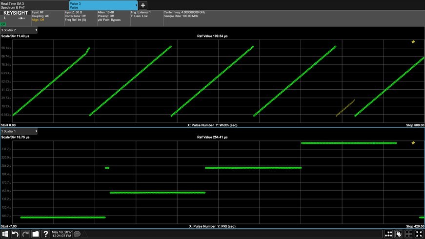
As seen in Figure 4, choosing to filter the repeating radar signal of interest highlights the intentional signal of interest and aids in the identification and detection of an unintentional signal.
Analyzing electronic attack techniques over time to determine effectiveness
Aside from parametric pulse analysis of radars and EW systems, there are times viewing both frequency and time domain characteristics is important to visualize technique operation. Tools like real-time spectrum analysis (RTSA) can aid with this challenge; however, there is a fundamental tradeoff between frequency resolution, acquisition time, and probability of intercept. This is an issue when attempting to simultaneously optimize both frequency and time domain analysis to validate range and velocity effects for EW techniques such as coordinated range gate pull off (RGPO) and velocity gate pull off (VGPO).
Use a coordinated RGPO/VGPO technique as an example to better understand the methods to measure both range and velocity simultaneously: Typical RTSA platforms rely on overlapped fast Fourier transforms (FFTs) and fast processing engines to acquire time domain samples without gaps. This acquisition is only optimized for a single view. However, with multiple acquisition boards being fed from the same analog-to-digital converter, decimation can be performed on the same samples, allowing for each acquisition board to be tuned to a different span. This flexibility is imperative since to measure Doppler shifts effectively in the frequency domain, as seen in Figure 5, a Doppler velocity pull of 5.934 kHz over 10 seconds. Conversely, wider bandwidths are needed for accurate rise/fall time resolution in the time domain, to see the pulses of interest changing 48.42.9 us over 10 seconds for the RGPO technique.
Figure 5: Duplex IF analysis
|
|

This duplex IF technique clearly shows the RGPO technique over time as shown in time domain as well as velocity effects in the frequency domain. It also enables the user to quantitatively understand if the desired jamming effect is correct based on technique rate and physics. This measurement technique presents a powerful method to visually confirm coordinated R/VGPO techniques.
Advanced measurement techniques, variable-length gated acquisition, and duplex IF RTSA greatly benefit the engineers designing and validating modern radar and EW systems being developed today as well as those who maintain legacy platforms that are still in service.
Philip Gresock is an application engineer for the Aerospace and Defense group of Keysight Technologies, focusing on high performance radar and EW signal-analysis platforms and measurement techniques. He has been with Agilent/Keysight for 8 years in application engineering and marketing. He received his BSEE from Michigan State University in 2007 and his MSEE from Lawrence Technological University in 2009.
Keysight Technologies • www.keysight.com